HAND
With nunchuck
The movement of the joystick of the nunchuck is translated by the arduino into a rotation of the servomotors that open or close the hand properly
With muscle sensor
When the arm is bent, the electrodes detect the muscle stimulus and send a signal to the arduino. The arduino translates it by activating the servomotors, one that pulls the wires and the other that releases them, inducing the fingers to bend. With another movement of the arm, the motors will be activated again, but in the opposite direction, bringing the fingers back to the starting position.
Construction
Materials
– Glove made of a material that is as elastic as possible.
– Finger caps, covering the last phalanges of each finger, with a hole at the top and one at the bottom, 3D printed.
– 0.8mm nylon fishing line.
– Two rings with 5 holes, where the threads will be knotted, 3D printed and small enough to slip between the glove and the hand; the holes are placed four in the front and one in the back.
– Two continuously rotating servomotors, with a wheel attached; attached to them will go strips of Velcro that will allow them to be attached to the arm.
Velcro strips.
– Three electrodes
Realization
1) Cut the fingers of the glove at the height of the first phalanx.
2) Knot the nylon threads to the caps, leaving them at a length that reaches the center of the hand.
3) Knot the other ends of the index, middle, ring and little finger wires to the two rings, one on the top of the hand above the glove, one on the bottom between the hand and the glove, which will then be positioned in the center of the hand.
4) Pass the thumb threads through holes in the center of the glove, created with a needle.
5) Knot two more nylon threads to the remaining empty holes in the rings.
6) Tighten the Velcro strips on the wrist so that they are immobile and cover a length of about ten centimeters.
7) Place the two servo motors at the bottom and top of the Velcro strips.
8) Knot the wires coming from the thumb and rings to the wheels of the respective servo motors.
9) Connect the servomotors with the arduino as shown in the electronics.
10) Connect the servomotors to the arduino.
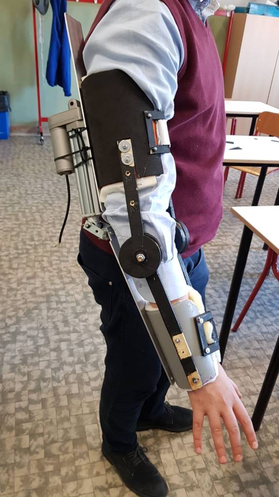
ARM
Operation
The structure of the arm is based on mechanical parts, respectively an electric actuator, an aluminum support system and a support base for the arm made from PVC tubes of various sizes.
1.1) Motor operation
The motor used is a linear actuator, that is an electric motor that under stimulus moves a shaft forward and backward in relation to the polarity provided, the current of use is about 2 Ampere at 12 Volt.
1.2) Functioning of the arm
Horizontal movement is converted to rotational movement using the person’s own elbow as the pivot and a system of belts and pins. There are 3 straps, one that adjusts the PVC pipe that adheres to the forearm, one that is at elbow height that keeps the forearm attached to the aluminum plate below and finally a strap that adjusts a PVC pipe that adheres to the arm. The PVC pipe of the forearm is 120 mm in diameter while that of the arm is larger, the diameter is 140 mm. The middle belt was added after the other two because we realized that the forearm did not adhere well to the plate, limiting the arc of the arm.
1.3) Electronics Operation
As power supply for the arm we used a 2200 mA drone battery, it is of small size and modest weight but still manages to give an autonomy on the hour of continuous operation. It powers the actuator passing through the button, it controls the polarity and the current, allowing the arm to move. The direction of the actuator will be derived from a DPDT(double pow double trow) button, which will control the polarity by reversing the direction. It has 3 modes, a central rest mode where the arm stays in place, an upward button press that will make the arm go up and a downward button that will make the arm go down.
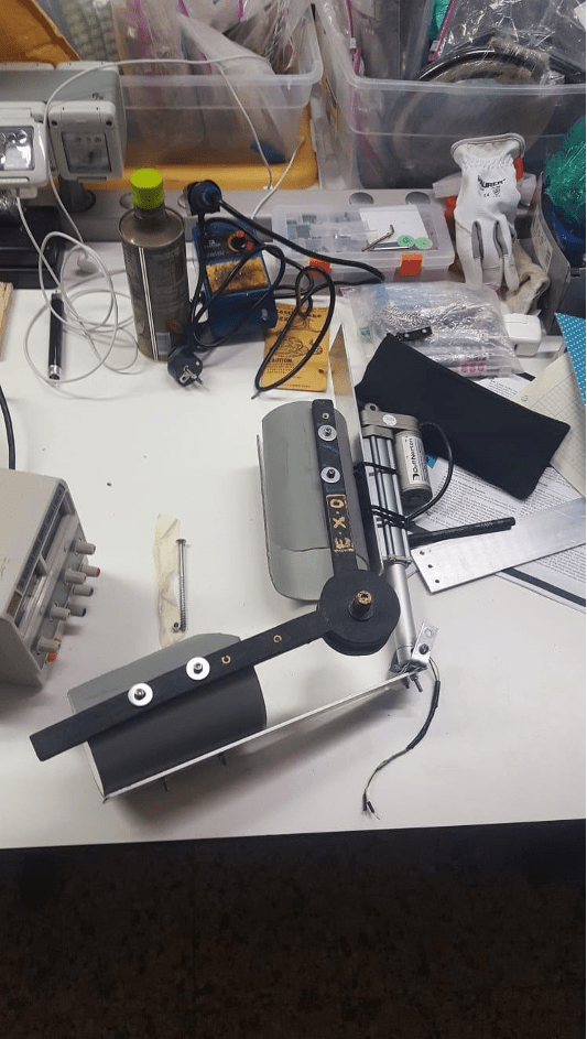
Construction
For the construction of the arm structure we used and modified an arm previously built by another member during a workshop in America.
We modified this arm with the prospect of building another one with improved comfort, since the support part was made of wooden parts the ease of wearing and comfort was reduced. Our primary goal was to make the arm more comfortable and less bulky.
2.1) First prototype:
In our first prototype we put in place of the two wooden planks two sheets of aluminum for strength, which eventually proved to be less bulky due to the smaller amount of aluminum needed compared to wood. However, the same linear actuator from the workshop prototype was used, due to the unavailability of other motors.
The project was first inspired by a privately built motor; a wiper motor was used in that project, which would have been simpler than the actuator. However, we decided to work with the actuator given the availability, although it had become necessary to have an apparatus to convert the horizontal movement to vertical, using the elbow and some wooden arms as a pivot.
For support, we used two 120 mm size PVC tubes covered with foam. The tubes were attached to the structure using screws and nuts to holes made with a drill. The actuator was attached to a rotating pin that imparted rotational motion to the upper part of the limb.
2.2) Second prototype
In the first prototype, we noticed several problems:
– It was too small for people
– It was uncomfortable
– It didn’t work well, the arm didn’t adhere to the lower aluminum part and wasn’t moved correctly
– The weight remained badly distributed
– Not properly anchored and was slipping off the arm
– Broke twice during testing
Our goal was to solve these problems, which made the previous prototype virtually unusable.
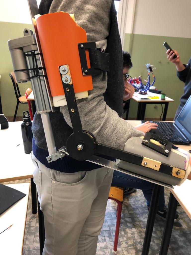
The first problem has been solved by applying a bigger tube (140 mm) in the upper part and a larger diameter, but leaving the smaller tube in the lower part, since it proved to be big enough.
The second problem was solved by putting some sponge inside the tube, this helped with friction and obviously with comfort, this sponge was fixed with simple hot glue; the sponge was already available inside the laboratory.
The third problem, among all the most serious, was not easy to solve, in the end we came to the conclusion that to make the arm adhere better to the aluminum the most efficient way was to add Velcro at elbow height, so that it is adjustable and immediate.
It was then applied a strap that goes over the shoulder as a support, it is connected by an additional strap to the arm itself, on this strap to the shoulder is mounted the electronics, the button and the battery.
One last problem that was revealed at the end was that the opening arc was not too small but too low, in fact the arm went from completely relaxed, perpendicular to the ground, to about a 90° angle, it was therefore decided to move the actuator forward, to allow it to go from about an angle of just under 90° to higher, to accomplish this process it was necessary to stretch an aluminum plate that held the actuator in place. However, an unforeseen problem arose when we moved the actuator forward; it tended to rotate not on the pivot we had built, but on a point of the plate; this movement, if restrained, could lead to the breakage of the arm.